
Services
Fiber Splicing & Installation
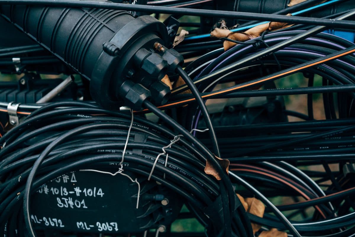
Fusion splicing, fiber placement, termination, and enclosure installation with bidirectional OTDR support and a recorded loss value for every fiber.
TLDR
Fiber splicing and installation joins, places, and terminates optical fiber so the finished span meets its loss budget. Strilla Communications performs fusion splicing, fiber blowing, pulling, termination, and splice enclosure installation across Volusia County and Central Florida, with bidirectional OTDR support, recorded splice loss, managed slack storage, and a documented closeout package.
What Splice Loss Should You Expect From a Fusion Splice?
A properly made fusion splice on matched single mode fiber is one of the smallest loss events on the whole route. The pass limit for each splice is set by the project specification and the network owner's acceptance criteria, usually as a bidirectional average, and clean work in a controlled environment lands consistently inside it. When a splice will not pass after two attempts, the problem is almost never the fusion settings.
The real causes sit upstream of the arc. A cleave angle out of tolerance, contamination on the fiber or in the V-grooves, coating residue left by a dull stripper, core geometry differences between two manufacturers, or a cable overtensioned during placement will all show up as loss at the splice point. We find and correct the cause instead of accepting a number that only looks acceptable from one direction.
Direction matters more than most specifications acknowledge. When two fibers with slightly different backscatter characteristics are joined, an OTDR reads elevated loss from one end and a gainer, an apparent negative loss, from the other. Neither reading is the truth. Averaging both directions produces the actual splice loss, which is why backbone acceptance testing should always be bidirectional.
Splice loss is also a budget line, not just a workmanship score. Every splice point, every patch panel, and every mated connector pair spends margin your optics need at turn up. If a design stacks enough splice points onto a long span to crowd the budget, we would rather say so during planning than hand you a passing splice log attached to a failing link.
- Cleave angle outside tolerance, usually from a worn blade or a rushed prep.
- Contamination on the fiber end face, in the V-grooves, or on the electrodes.
- Coating residue left behind by a stripper that needs replacing.
- Mismatched fiber types or core geometry between two cable manufacturers.
- Fiber stressed during placement by overtension, tight bends, or crushing.
- Protection sleeves not fully seated or shrunk unevenly in the heater.
How Your Loss Budget Adds Up Before Anyone Splices
The link budget is decided in design, and splicing either fits inside it or it does not. Fiber attenuation over the route, splice count, connector count, any passive splitters, and a reserve for future repairs all come out of the same number the optics can tolerate between transmitter and receiver.
Single mode fiber attenuates less at 1550 nm than at 1310 nm, so a span can pass at one wavelength and fail at the other for reasons that have nothing to do with distance. 1550 nm is the wavelength that exposes macrobends, because bend loss climbs sharply as wavelength increases. A span that reads clean at 1310 nm and shows an unexplained step at 1550 nm usually has a coil pulled too tight, a cable pinched in a duct, or slack stored on a radius the cable was never rated for.
Splitters dominate the budget on PON distribution. A split ratio consumes a fixed block of loss before the fiber leaves the cabinet, which leaves far less headroom for splice and connector losses downstream. Backbone spans are the opposite case: few components, long distance, and attenuation over kilometers doing most of the spending.
Repair margin is the piece most often left out. Every future cut, whether from an excavator, a vehicle strike on a pole, or a storm, adds a pair of splices and a length of replacement cable. A link built with no headroom passes on day one and fails after its first repair. We keep that in view when we recommend splice locations, and we say so when a design leaves nothing in reserve.
- Fiber attenuation across the full route length at both test wavelengths.
- Loss at every fusion splice, counted from the splice plan rather than estimated.
- Loss at every mated connector pair, including the patch panels at each end.
- Splitter loss where the architecture is PON.
- Reserve margin for future repair splices and replacement cable.
OTDR Testing: What It Proves and What It Misses
An OTDR shows you where events sit along a fiber and roughly what each one costs. It is the right instrument for locating a bad splice, a tight bend, a crushed section, or a break, and it is the only practical way to characterize a long span from one end. It is not a measurement of end to end insertion loss.
Insertion loss comes from a light source and a power meter, one at each end, referenced before the test. That pair of readings is what an optical link actually experiences. An OTDR infers loss from backscatter, which is why two directions disagree on the same splice and why the first and last connectors are difficult to see at all without launch and receive fibers.
Launch and receive fibers are not optional on an acceptance test. Without a launch cord, the near end connector sits inside the instrument dead zone and its loss is invisible. Without a receive cord, the far end connector has no fiber behind it to backscatter, so it cannot be measured either. Those two connectors are the ones most likely to be dirty.
Pulse width is the tradeoff you set before you press start. A short pulse resolves closely spaced events but does not reach far. A long pulse reaches the end of a long span but merges nearby events into one and can hide short sections entirely. We test long spans at more than one pulse width when the splice spacing calls for it, instead of accepting a single trace that averages the detail away.
We support your testing however your acceptance process is written. That can mean we test and deliver the traces, we test alongside your technician, or we make the plant ready and stand by while your team or a third party certifies it. In every case the traces, the splice records, and the fiber assignments have to agree with each other, and we check that they do before anything is sent.
Slack Storage Decisions You Live With for Years
Slack is the difference between a two hour repair and a two day one. When a cable is cut, the crew needs enough fiber on both sides to reach a splice trailer or a controlled work area, plus enough to make the splice without stressing the cable. Slack trimmed short to tidy a handhole is the reason a future outage runs long.
Where slack goes depends on the plant. Underground, it coils in a vault or handhole large enough to hold the coil at a radius the cable tolerates, secured so it does not rest in standing water or shift under a lid. Aerial, it stores on snowshoes or storage brackets sized to the cable, mounted where a bucket can reach it and where the span will not sag into a clearance problem.
Bend radius governs every coil. Cables carry a minimum bend radius for installation under load and a smaller one for long term static storage, and both come from the manufacturer, not from what happens to fit the enclosure. A coil forced into an undersized vault can read fine on the installation trace and slowly get worse. That is the failure that surfaces at 1550 nm months later.
We also place slack where it will be useful. That means extra length at road crossings and bridge attachments, at points where the cable transitions between aerial and underground, near equipment that will be replaced during the life of the plant, and at any location where a locate ticket is likely to bring a machine close to the cable. Slack in the right place is cheap. Slack in the wrong place is just weight.
- Coil diameter held above the cable long term bend radius, not sized to the enclosure.
- Enough length at each splice point to reach a splice trailer or other controlled work area.
- Additional slack at crossings, aerial to underground transitions, and future equipment sites.
- Aerial slack on correctly sized storage brackets, clear of the clearance envelope.
- Underground slack secured off the floor of a vault that will hold water seasonally.
What Good Enclosure Workmanship Looks Like
An enclosure either stays sealed for decades or it becomes the place your network fails. The difference is prep work you can see the moment the lid comes off: jackets stripped to the correct length, strength members anchored to the bracket instead of to a tray, buffer tubes routed on a radius rather than folded into place, and every tube landed in the order the splice plan calls for.
Sealing is a system, not a gasket. Gel sealed closures need clean, correctly prepared jackets and even compression across the seal. Heat shrink entries need the jacket abraded and cleaned, the sleeve centered, and heat applied evenly until adhesive flows all the way around the entry. Unused ports get plugged, not taped. Where the closure supports it, we pressure test before it goes into the ground or up onto the strand.
Bonding and grounding get skipped more often than any other step. Armored cable carries a metallic member that has to be bonded and grounded per the design, and ungrounded armor near a Florida lightning strike is a path toward your equipment. We bond it, and the closeout shows where.
Tray discipline is what makes the next technician's job possible. Fibers routed with their excess length parked in the tray, protection sleeves seated in their holders, tubes labeled, and trays loaded so the one you need is not buried under three others. A closure that has to be dismantled to reach one fiber turns a small repair into a risk to every other circuit in the case.
Labeling closes the loop. Cable identification at every entry, tray and buffer tube identification that matches the splice matrix, and enclosure identification that matches the as built. If the label in the field and the record in the file disagree, the record is worthless the first time someone works that plant at night.
Placing the Cable: Blowing, Pulling, and Aerial Handoffs
Splicing is only as good as the cable it joins, and most fiber damage happens during placement. Overtension, a bend taken around a sharp corner, or a jacket dragged across a broken duct edge produces attenuation no splice technique can recover. The placement method should be chosen from duct condition, route length, and cable design, not from whatever equipment happens to be on the truck.
Blowing, also called jetting, floats the cable on airflow so tension stays low across long continuous runs. It performs well in clean, proofed duct and microduct, and it can place a run in a single shot where pulling would need intermediate access points and the splices that come with them. It also depends completely on duct integrity, which is why we verify duct before a blow rather than during one.
Pulling is the answer for shorter sections, congested duct that already holds cable, transitions through vaults, and any run where a pull line is already in place. It demands monitored tension, the correct swivel and grip setup, sheaves and quadrant blocks at every direction change, and lubricant matched to both the jacket and the duct material.
Aerial placement adds its own handoffs. Cable is lashed to strand, then transitions into a closure on the pole or drops into a riser and continues underground. Those transition points are where slack, bend radius, and grounding decisions all land at once, and they deserve to be planned rather than improvised in the field. We build both the aerial and the underground side, so the transition is designed by the people who have to splice it.
Splicing in Florida Conditions
Humidity and heat are the working conditions here, not the exception. Fusion splicing wants a controlled environment, so production splicing happens inside an enclosed work area, such as a splice trailer or tent, with power, a clean bench, and protection from heat and humidity. Splicing on a tailgate on an August afternoon produces exactly the loss numbers you would expect from it.
Afternoon storms decide the sequence of the day. An open closure, an exposed cable end, and a bucket in the air are all the wrong places to be when a cell moves through. We stage work so an opened closure can be sealed before the weather turns, and so an exposed cable end is capped rather than left overnight.
Water is the other constant. A high water table and heavy seasonal rain mean vaults and handholes hold water for part of the year, and any closure placed in one has to be rated and sealed on the assumption that it will be submerged. Coastal routes add salt to the same problem, which shows on hardware, brackets, and pedestal bases long before it shows on the fiber.
Lightning is not a rare event on this coast. Bonding and grounding of armored cable, enclosures, and pedestal hardware is treated as installation work with a documented result rather than as a formality. That matters most where fiber shares a route with power and where a copper element runs alongside it.
Which Fiber Service Does Your Project Actually Need?
Most projects need more than one of these services, and the split depends on what is already built. A route with conduit in the ground and no cable needs placement first, then splicing, then termination. A route where cable is already placed and coiled at each structure needs splicing, enclosures, and testing. A cut cable needs all of it at once, compressed into a restoration window.
Placement method is the first fork. Blowing suits long, clean, empty duct and microduct, where low tension and fewer splice points pay off. Pulling suits shorter sections, vault transitions, occupied duct, and conduit that already holds a pull line. Aerial cable is lashed to strand, which is covered under our aerial construction work and handed off to splicing at the pole closures.
Splicing and enclosure work usually travel together, because the closure is where the splices live. Termination is the last step on each end of a span, where field fiber becomes a connector that equipment can plug into. Testing runs through all of it, and the acceptance method should be agreed before the first reel is staged.
- Fusion splicing: joining fibers at closures, panels, and repair points, with a recorded loss for every fiber.
- Fiber blowing: jetting cable into proofed duct or microduct over long runs at low tension.
- Fiber pulling: winch placement through conduit with monitored tension and correct rigging.
- Fiber termination: pigtail splicing and connectorization at panels, cabinets, huts, and demarcation points.
- Splice enclosure installation: closure prep, sealing, bonding, mounting, slack, and labeling.
How Does Splicing Fit Into the Rest of an Outside Plant Build?
Splicing is the step that turns separate cable sections into a working network, so it sits near the end of the build and inherits every decision made before it. Bore depth, conduit routing, handhole placement, aerial attachment heights, and slack left at each structure all show up at the splice bench. A splice crew working behind a drilling or aerial crew it has never spoken to is where schedule slips start.
We build the drilling, conduit, aerial, and fiber pieces ourselves, which means the people who place a handhole know the closure that will sit in it and the slack it needs. That is not a guarantee every structure ends up where the plan put it. It does mean the handoff between placement and splicing is a conversation inside one company rather than a dispute between two.
Sequencing matters for testing as well. Spans can be tested as soon as they are spliced, before the next section is complete, so a problem in one segment shows up while the crew that built it is still nearby. Waiting to test the whole route at the end compresses every fix into the last week of the schedule, right when the owner wants to turn up service.
The splice plan is the document that ties it all together. It should exist, match the cable that was actually ordered, and be approved before splicing starts. When it changes mid project, which happens, the revision should be dated and issued to the crew in writing so the field record and the design record stay the same document.
What You Receive at Closeout
A splice job is not finished when the last fusion is made. It is finished when your records let someone who was never on site find the splice point, open the right tray, and identify the right fiber. That package is part of the work, not an extra line item at the end of it.
The splice record is the core document: cable to cable fiber assignments, tray and position, the loss reading for each fiber, and the technician and date. It is the file your NOC opens at two in the morning, so it has to match the labels in the field exactly.
Test results travel with it. Bidirectional OTDR traces at the wavelengths your specification calls for, delivered in native trace format so your engineers can reopen them and in a readable summary for the project file, plus light source and power meter insertion loss results where your acceptance process requires them.
The rest is location and condition evidence: enclosure photographs before and after closing, coordinates or stationing for every splice point and vault, slack storage locations and lengths, as built redlines showing what was actually placed, and daily production reporting through the job so the closeout is a compilation rather than a reconstruction.
- Splice matrix with per fiber loss values, tray positions, and cable identifiers.
- Bidirectional OTDR traces in native format plus a readable test summary.
- Light source and power meter insertion loss results where specified.
- Enclosure and slack storage photographs, before and after closing.
- Coordinates or stationing for every splice point, vault, and slack coil.
- As built redlines and daily production reports compiled through the job.
Key takeaways
- A fiber span is accepted on bidirectional test results measured against the project specification, not on the splicer's loss estimate.
- Most high splice loss comes from preparation or placement damage, so rework starts with finding the cause rather than re-arcing the fiber.
- An OTDR locates and characterizes events along a fiber, while a light source and power meter measure the true end to end insertion loss.
- Slack left at each splice point decides how long a future repair takes, so it is a design decision rather than leftover cable.
- A closeout package is only useful when the splice records, trace files, and field labels all agree with each other.
Key terms
- Fusion splice
- A permanent joint made by aligning two prepared optical fibers and melting them together with an electric arc. The fused section is covered with a heat shrink protection sleeve and stored in a splice tray inside a closure or panel.
- OTDR (optical time domain reflectometer)
- A test instrument that sends light pulses down a fiber and reads the light scattered back. It shows the distance to each splice, connector, bend, or break and estimates the loss of each event, which makes it the main tool for locating problems on a span.
- Insertion loss
- The total optical power lost between two ends of a link, measured with a calibrated light source at one end and a power meter at the other. It includes fiber attenuation, splices, and both end connectors, so it reflects what the network equipment will actually experience.
- Loss budget
- The total loss a link can tolerate between transmitter and receiver, set during design. Fiber attenuation, every splice, every connector pair, any passive splitter, and a reserve for future repairs all draw from the same budget, and the finished link must fit inside it.
- Splice matrix
- The record that maps every fiber in one cable to its matching fiber in another at a splice point, with tray and position, loss value, technician, and date. It is the document a network operations team uses to trace a circuit through the field.
| Service | Best suited to | Main risk if done poorly | What we verify |
|---|---|---|---|
| Single fiber fusion splicing | Loose tube cable, drops, repairs, mixed cable types | High loss from poor cleaves or contamination | Bidirectional OTDR loss on every fiber |
| Mass fusion ribbon splicing | High count ribbon and rollable ribbon cable | A bad cleave affects a whole ribbon at once | Per fiber loss after each ribbon splice |
| Fiber blowing | Long runs in clean, empty duct or microduct | Stalled cable in damaged or leaking duct | Duct proofing before the reel is staged |
| Fiber pulling | Short sections, vault transitions, occupied duct | Overtension and bend damage during the pull | Monitored tension and radius at every guide point |
| Fiber termination | Panels, cabinets, huts, and demarcation points | Dirty or mismatched connectors at turn up | End face inspection and insertion loss |
| Splice enclosure installation | Vaults, handholes, pedestals, strand, and walls | Water entry and unbonded armor | Seal method, pressure test where supported, bond photos |
What this means for your project
Splicing is where an outside plant project either closes on schedule or stalls in the last few weeks. Problems that started earlier, such as short slack, stressed cable, or a splice plan that does not match the cable on the reel, surface at the splice bench and at acceptance testing. Bringing the splicing scope into planning, with the test method and acceptance criteria agreed up front, moves those discoveries to the start of the job where they are cheap to fix.
Cost risk follows the same pattern. A failed span found during testing with the closure still open is a short rework at the bench. The same failure found after the closure is sealed, buried, or lifted onto the strand means a return trip, traffic control, and sometimes an excavation. Testing each span as it is spliced, rather than the whole route at the end, keeps rework small and keeps your turn up date intact.
Documentation is the part that outlives the project. Your operations team will open the splice matrix and the trace files years from now, often during an outage. A closeout package where records, traces, and field labels agree is what lets a crew that was never on the original job find the right tray and the right fiber at night, and it is a deliverable you should expect from any splicing contractor.
Related reading
- How fiber splicing is performed in the fieldA step by step guide to field splicing, from cable prep to the final trace.
- Backbone constructionLong haul and middle mile builds where splice count and loss budget matter most.
- Conduit installationThe duct systems that fiber is blown or pulled into before splicing.
- As-built documentationRedlines and records that tie splice points to real field locations.
- Closeout and documentation standardsWhat a complete fiber closeout package should contain.
- Outage restorationCut cable repair and restoration splicing on in service plant.
- Fiber installation projectsThe types of fiber placement and splicing work we take on.
- Working with OSP engineersHow we work with the engineers who write splice plans and acceptance specs.
What's Included
- Single fiber and mass fusion splicing, with a loss value captured for each fiber rather than sampled.
- Splice enclosure installation in vaults, handholes, pedestals, on strand, and on building walls.
- Bidirectional OTDR testing at the wavelengths your acceptance specification requires.
- Light source and power meter insertion loss testing for true end to end link values.
- Fiber placement by blowing or pulling, selected from duct condition, route length, and cable design.
- Termination and connectorization at patch panels, cabinets, huts, and demarcation points.
- Slack storage placed and secured at coil radii the cable manufacturer allows.
- Bonding and grounding of armored cable and enclosure hardware, documented as installed.
- Emergency restoration splicing with rapid mobilization when an in service span is cut.
- Splice matrix, trace files, photographs, and as built redlines delivered as one closeout package.
Our Fiber Splicing Process
- 01
Splice Plan and Fiber Assignment Review
We read your splice plan against the cable that is actually in the ground or on the strand before anyone opens a closure. Fiber counts, buffer tube color order, cable identifiers, and tray assignments get reconciled first, because a mismatch found at the bench costs minutes and the same mismatch found at turn up costs a truck roll.
- 02
Cable Placement and Slack Staging
Cable is blown, pulled, or lashed into position with tension and bend radius controlled throughout, then slack is measured and staged at each splice location. Coils are sized to the cable, not to the vault, and enough length is left at every splice point to reach the splice trailer without stressing the cable.
- 03
Cable Preparation and Enclosure Setup
Jackets are stripped to the closure manufacturer's dimensions, strength members are anchored to the bracket, armor is bonded, and buffer tubes are routed into trays on a radius. Entry ports are sealed as the closure is designed to be sealed, and unused ports are plugged rather than covered.
- 04
Fusion Splicing and Tray Loading
Fibers are stripped, cleaned, cleaved, and fused in the order the splice plan calls for, with the machine loss estimate reviewed on each splice and any outlier reworked immediately. Protection sleeves are shrunk fully and seated in their holders, and each tray is loaded so it can be lifted later without disturbing the trays beneath it.
- 05
Acceptance Testing
Spans are tested bidirectionally by OTDR with launch and receive fibers at the wavelengths your specification names, and insertion loss is measured with a light source and power meter where the acceptance process calls for it. Results are compared against the threshold before the closure is sealed, so a rework is a bench operation rather than a return trip.
- 06
Closure, Labeling, and Documentation
The enclosure is sealed, pressure tested where the design supports it, mounted, and photographed. Cables, trays, and the enclosure itself are labeled to match the splice matrix, slack is secured, and the splice record, traces, photographs, and locations are compiled into the closeout package with your daily reports.
Capability Overview
| Splice types | Single fiber fusion, mass fusion ribbon, mechanical for temporary restoration |
|---|---|
| Fiber types | Single mode including bend insensitive, multimode where existing plant requires it |
| Acceptance threshold | Set by the project specification and the network owner's acceptance criteria, bidirectional average |
| Test wavelengths | 1310 nm and 1550 nm single mode, 1625 nm on request, 850 nm and 1300 nm multimode |
| Test methods | Bidirectional OTDR with launch and receive fibers, light source and power meter insertion loss |
| Connector types | LC, SC, ST, FC, and MPO style, UPC or APC polish |
| Enclosure environments | Vault, handhole, pedestal, aerial strand mount, riser, wall mount, cabinet |
| Placement methods | Jetting into duct and microduct, winch pulling, aerial lashing to messenger strand |
| Deliverables | Splice matrix, native traces, test summary, photographs, splice point locations, as built redlines |
Fiber Splicing & Installation Services
- Fusion SplicingSingle fiber and mass fusion splicing for outside plant fiber in Florida. Controlled cleaving, bidirectional OTDR verification, and a per fiber loss record.
- Fiber BlowingFiber blowing and jetting into HDPE duct and microduct across Florida. Duct proofing, low tension placement, and continuous runs with fewer splice points.
- Fiber PullingFiber optic cable pulling through Florida conduit and duct. Monitored pulling tension, correct swivel and grip rigging, lubrication, and bend radius control.
- Fiber TerminationFiber termination and connectorization in Florida: pigtail splicing, patch panel build out, end face inspection, and insertion loss testing before turn up.
- Splice Enclosure InstallationSplice closure installation for buried, aerial, and pedestal fiber plant in Florida. Correct jacket prep, sealed re-enterable closures, bonding, and labeling.
Frequently Asked Questions
- What splice loss do you test to?
- We work to the threshold your specification sets. The per splice limit is set by the project specification and the network owner's acceptance criteria, and it is almost always measured as a bidirectional average. Good work on matched single mode fiber typically lands comfortably inside it. If a splice will not meet the threshold after rework, we investigate the cause, whether that is fiber mismatch, cable damage from placement, or a preparation problem, rather than reporting the better of two directions.
- Do you provide OTDR traces, or does our engineer do the testing?
- Either arrangement works. We can test and deliver bidirectional traces in native format with a readable summary, we can test alongside your technician so both parties sign off in the field, or we can build and prepare the plant and stand by while your team or a third party certifies it. Tell us which model your acceptance process uses before we mobilize so the schedule accounts for it.
- How much slack do you leave at each splice point?
- Enough to reach a splice trailer or work area from the enclosure and make a repair without stressing the cable, stored at a coil radius the cable manufacturer permits. Your specification usually sets the figure, and we follow it. Where a spec is silent, we recommend a length based on the access at that location, and we record the actual length and storage position in the closeout so a future crew knows what is there.
- Can you splice into an existing live cable?
- Yes. Working on in service plant means coordinating a maintenance window, confirming which fibers are dark and which are carrying traffic, and preparing the closure and slack before anything is cut. We identify the fibers against your records first, stage the work so exposure time is short, and test immediately after so any circuit that comes back wrong is caught while the crew is still on site.
- What drives how long splicing takes on a span?
- Fiber count, cable design, and access, in that order. Mass fusion joins an entire ribbon in one cycle while loose tube cable is spliced fiber by fiber, so two cables of the same count can differ substantially. Access matters just as much: a closure in a dry vault with a truck alongside moves faster than one in a flooded handhole in an active travel lane needing traffic control.
- Do you handle emergency restoration splicing after a cut?
- Yes. Cut cable restoration is a standing part of our work, including locating the damage, exposing the cable, placing replacement length, and splicing both ends. Where a service has to come back before a permanent repair is possible, temporary methods can restore traffic and the permanent splice follows on a scheduled window. Call the office directly for an outage rather than sending it through a project queue.
- What areas do you cover for splicing work?
- Volusia County is our primary service area, Central Florida including Orange, Seminole, Osceola, Lake, and Polk counties is served routinely, and we take statewide Florida work where the project scope justifies mobilization. Splicing crews bring an enclosed work setup to the site, so a remote route does not force bench work to happen on a tailgate.
- Do you work from our splice plan or create one?
- We work from your splice plan when one exists, and we review it against the cable actually placed before any fiber is cut. Where a project has no formal plan, we can build the fiber assignments with your engineer from the design intent, then issue them for approval before splicing starts. Either way, the plan the crew splices to is the same document that goes into the closeout record.
- Who supplies the splice closures, trays, and pigtails?
- Either party can, and the bid should say which. Owner supplied material is common on larger networks with standardized closures, and in that case we need part numbers early so prep dimensions and tray capacity are known. When we supply material, we select it from the environment, the fiber count, and the adds your plan expects, then confirm the selection with you before ordering.
- What should we send you to get an accurate splicing quote?
- Send the splice plan or fiber counts, the number and location of splice points and termination panels, the cable type, and who supplies material. Add the test method and wavelengths your acceptance process requires, any live plant or outage window constraints, and the closeout format you need. With those details we can price crew days accurately instead of padding for unknowns, and we will flag anything missing.
Related Services
- Directional DrillingTrenchless directional drilling for fiber and utility conduit across Volusia County and Central Florida, planned against verified locates and closed out with documented bore logs.
- Aerial Cable ConstructionPole line construction, strand placement, lashing, and aerial fiber installation with make-ready coordination and NESC clearance verification.
- Conduit InstallationHDPE duct, innerduct, and microduct placed by bore, trench, or plow, proofed with a mandrel, and made locatable with tracer wire and marker tape.
- System MaintenanceContract maintenance for aerial and underground plant: scheduled inspection cycles, optical testing, locating, and permanent repairs under one agreement.
- Emergency Service RestorationUnplanned repair work that puts a damaged fiber or conduit network back in service after a cut, a storm, or a failure, followed by permanent repair and a documented closeout.
- Outside Plant ConstructionTurnkey OSP construction that carries a fiber build from permitting and boring through aerial, splicing, restoration, and a documented closeout.
Request a Bid
Need fiber splicing & installation on your next build?
Send the scope, footage and location. Most bid requests get a response within one business day.
Most bid requests receive a response within one business day.